I have been data gathering for almost a month now. Here is the last week's data. Saturday and Wednesday were foggy days! Typical SF summertime weather...
And for the last month:
When the panels where dry, before I turned on the controller/pump, the low was about the same, but the high was 190 C (375 F), not 90 C (194 F). Most of the cooler days indicate presence of our lovely fog.
Tuesday, August 12, 2014
Tuesday, July 15, 2014
Data Logging: Results!
As of last night I completed hookup of the eighth 1-wire temperature sensor. It is reading at the hot inlet to the mixing valve, which is also the outlet to my old 30 gallon hot water heater. This will give me an idea of the performance of the mixing valve and it's settings, as the difference between the "Domestic Hot Water Supply" and the measurement read at this sensor is how much cold water is being mixed into my hot water supply.
The data that I am generating is being put, for each sensor, into an RRDtool database every 30 seconds. I have no idea what a good sampling frequency is, so I settled on this one because it sounded about right. I will probably blow away this database and recreate it a few times in the next week or so trying to get it 'just right'.
Here is the dataset for the last four hours today:
The lines I found most interesting are the roof (red), solar storage tank temperature (green) an domestic hot water supply (should be magenta, but looks red!). DHW supply roughly shows the usage during the afternoon. I very much dig the slow but steady rise of the storage tank temperature!
The data that I am generating is being put, for each sensor, into an RRDtool database every 30 seconds. I have no idea what a good sampling frequency is, so I settled on this one because it sounded about right. I will probably blow away this database and recreate it a few times in the next week or so trying to get it 'just right'.
Here is the dataset for the last four hours today:
The lines I found most interesting are the roof (red), solar storage tank temperature (green) an domestic hot water supply (should be magenta, but looks red!). DHW supply roughly shows the usage during the afternoon. I very much dig the slow but steady rise of the storage tank temperature!
Tuesday, July 8, 2014
Time to start Datalogging
My system has been running for almost a year now. I've been busy raising our twin girls, now a year old, and the solar system 'hobby' has faded into the background. I get started getting tiny time slices for projects in the last couple months, usually between nine and ten at night on weeknights. With some of that time my next addition to the system is data logging.
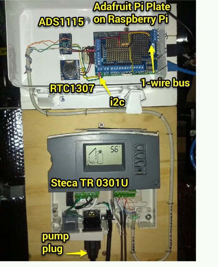
An Arduino Uno with ethernet shield and microSD storage was my first thought for a data logger. It is economical, available with great libraries, sample code and forum support. I got a little ways down the road using one and then realized it would be so much easier with a Raspberry Pi, add-on 16-bit ADC (ADS1115) and 1-wire thermal sensors (the ubiquitous Maxim ds18b20). My money making gig is as a Linux administrator, so working with Raspbian on the Pi is a simple pleasure for me. Also, getting Network Time Protocol (NTP) and a Real Time Clock (RTC) working on the Pi is simpler. I ended up getting a DS1307-based RTC that works over i2c. It's plenty accurate when paired with NTP which will give me good timestamps for my time series data. To make interfacing all these devices easier to my Raspberry Pi, I'm using the Adafruit Pi Plate (see below).
The ADC is used to read voltages on the two temperature sensors (located at the panel output header and storage tank) that came with the Steca controller. The voltage range that it presents is pretty small - 64F/2.040V - 176F/2.200 - so I'm happy having the 16-bit ADC rather than the Arduino's 10-bit ones. In the image below you can see how I have used and orange and green pair from CAT5 cable to tap into the roof and storage tank thermal probe leads.
I ordered 10 1-wire sensors from Amazon that were nicely soldered onto cables with stainless shrouds protecting the sensors. I hope they will withstand years of hot water temperatures. Five of them are now patched into a 12-port patch panel which I am using as a combined 1-wire and ethernet patch panel. The ethernet patch is for the Pi. For the 1-wire bus, three conductors in the CAT5 cable - blue (data), green (ground), and orange (power) - will extend the sensor wire to the panel. I'm using 568B wiring style in all the jacks regardless of whether it's ethernet or 1-wire. I borrowed a buddy's 110 impact punch down tool to connect all the wires easier (Thanks Peter!). Here's the back of the patch panel:
Happily all the 1-wire sensors are working. I'm happy about this as each sensor connection required crimping one RJ45 jack, soldering three leads and punching down three wires. There was plenty to screw up and I didn't. woO! The two ADC connection to the roof and storage tank temperature sensors are also reporting their temps to a python script that uses the adafruit ADS1115 libraries. The completed setup is below. I'm kind of dreading writing all the code - there are a lot of decision to make about it - but at least most of the HW setup is done.
An Arduino Uno with ethernet shield and microSD storage was my first thought for a data logger. It is economical, available with great libraries, sample code and forum support. I got a little ways down the road using one and then realized it would be so much easier with a Raspberry Pi, add-on 16-bit ADC (ADS1115) and 1-wire thermal sensors (the ubiquitous Maxim ds18b20). My money making gig is as a Linux administrator, so working with Raspbian on the Pi is a simple pleasure for me. Also, getting Network Time Protocol (NTP) and a Real Time Clock (RTC) working on the Pi is simpler. I ended up getting a DS1307-based RTC that works over i2c. It's plenty accurate when paired with NTP which will give me good timestamps for my time series data. To make interfacing all these devices easier to my Raspberry Pi, I'm using the Adafruit Pi Plate (see below).
The ADC is used to read voltages on the two temperature sensors (located at the panel output header and storage tank) that came with the Steca controller. The voltage range that it presents is pretty small - 64F/2.040V - 176F/2.200 - so I'm happy having the 16-bit ADC rather than the Arduino's 10-bit ones. In the image below you can see how I have used and orange and green pair from CAT5 cable to tap into the roof and storage tank thermal probe leads.
I ordered 10 1-wire sensors from Amazon that were nicely soldered onto cables with stainless shrouds protecting the sensors. I hope they will withstand years of hot water temperatures. Five of them are now patched into a 12-port patch panel which I am using as a combined 1-wire and ethernet patch panel. The ethernet patch is for the Pi. For the 1-wire bus, three conductors in the CAT5 cable - blue (data), green (ground), and orange (power) - will extend the sensor wire to the panel. I'm using 568B wiring style in all the jacks regardless of whether it's ethernet or 1-wire. I borrowed a buddy's 110 impact punch down tool to connect all the wires easier (Thanks Peter!). Here's the back of the patch panel:
Happily all the 1-wire sensors are working. I'm happy about this as each sensor connection required crimping one RJ45 jack, soldering three leads and punching down three wires. There was plenty to screw up and I didn't. woO! The two ADC connection to the roof and storage tank temperature sensors are also reporting their temps to a python script that uses the adafruit ADS1115 libraries. The completed setup is below. I'm kind of dreading writing all the code - there are a lot of decision to make about it - but at least most of the HW setup is done.
Monday, July 29, 2013
Since I last entered anything on this blog I had twin girls and my baby is now almost four years old. How time flies!
Today I plugged in the Grundfos pump and after a few minutes felt the return pipe get very hot. It was a cloudy day here in SF, so I took that to be a good sign. Shortly after the pipe heated up, the flow dropped to zero even as the pump worked hard to move the water. At this point I had only added five gallons of tap water. The drainback tank is 7.5 gallons, the heat exchange loop in my SunEarth tank is 2.2 gallons and the balance of piping is maybe another 0.5 gallons. That makes around 10 gallons of water to fully fill the drainback tank, which is above the height of the heat exchanger, pump and balance of piping. After adding another ~5 gallons, the water flowed once more and the bubbles began to get smaller, then mostly disappear.
I used tap water to simply flush the system of flux and 'funk' before adding distilled water.
I found that I needed to run the pump awhile to fully charge the system. I suspect air gets trapped here and there, and needs a good push to get evicted.
All the plumbing is finished. I now need to:
1. Insulate the the inside piping.
2. Solder the temperature probe on the roof to the bell wire that I've run up to the panels and run that to the array outlet.
3. Find a source for outdoor grade pipe insulation and install.
4. Add Reflectix insulation to exposed parts of the drainback tank and add a layer of it to the storage tank.
5. Test the Steca controller and then choose settings for it.
woO!
Today I plugged in the Grundfos pump and after a few minutes felt the return pipe get very hot. It was a cloudy day here in SF, so I took that to be a good sign. Shortly after the pipe heated up, the flow dropped to zero even as the pump worked hard to move the water. At this point I had only added five gallons of tap water. The drainback tank is 7.5 gallons, the heat exchange loop in my SunEarth tank is 2.2 gallons and the balance of piping is maybe another 0.5 gallons. That makes around 10 gallons of water to fully fill the drainback tank, which is above the height of the heat exchanger, pump and balance of piping. After adding another ~5 gallons, the water flowed once more and the bubbles began to get smaller, then mostly disappear.
I used tap water to simply flush the system of flux and 'funk' before adding distilled water.
I found that I needed to run the pump awhile to fully charge the system. I suspect air gets trapped here and there, and needs a good push to get evicted.
All the plumbing is finished. I now need to:
1. Insulate the the inside piping.
2. Solder the temperature probe on the roof to the bell wire that I've run up to the panels and run that to the array outlet.
3. Find a source for outdoor grade pipe insulation and install.
4. Add Reflectix insulation to exposed parts of the drainback tank and add a layer of it to the storage tank.
5. Test the Steca controller and then choose settings for it.
woO!
Thursday, September 6, 2012
Panels Racked
Both chalk lines are snapped (fluorescent orange). The bottom and top rails will anchor to the FastJacks that dot these lines. There are a total of six them. The sealent under the jacks is a Geocel roof caulking product (GeoGreen 4500?). Stainless steel lag bolts hold the jacks to the roof. Final tightening of the bolts is done manually with a ratcheting socket wrench.
Bottom end panels will be anchored at the above three jacks.
Ron starts applying APOC 133 roof sealant around jack. Behind him you can see the Oatey flashing that have been sprayed with the sealant primer - a sticky black coating on both sides.
Oatey solar roof flashings come next. The above flashing didn't have the sticky spray applied to it, so we had to remove it and try again. Over the APOC 133 we placed strips of fiberglass tape (not shown) to help strengthen the sealant layer.
The Oatey flashing and the area around it is covered in APOC 133, then the roll roofing material is laid over. Each piece is 2'x2'.
The stainless "self-tapping" screws that came with the SunEarth RexRack did not want to penetrate the rails. They're tough rails! So were were forced to predrill the rails first. We broke a total of three bits doing this. Ron remarked that he'd not worked with such recalcitrant rail before.
The back rail is fully installed.
The two 4'x8' panels are up and mounted. The headers on these panels have not been coupled, they're just clamped to the rails. Now it's up to me to sweat two couplers on the middle heaters to attach panel to panel. On the outside headers I need to cap one on the top and one on the bottom. The other two outside headers need 1" to 3/4" reducing fittings installed and elbows to point back to the supply pipes. I need to determine if this system requires pressure relief valve or not given that it's a drainback design.
Thursday, August 30, 2012
Goop on the Roof
1. Wire brushing the existing gravel surface of my rolled roofing.
2. Applying a 3-5 mm layer of the APOC 133 roof sealant.
3. Back buttering the Oatey `Solar' flashings with APOC 133 and sticking them on the roof.
4. Forgetting to pull the sensor wire through the flashing. (DOH!)
5. Overlapping the flashing and threading them down the plumbing pipes.
6. Covering the flashing with more APOC 133.
7. Cutting a square of bitumen rool roofing to cover the goo.
8. Peeling backing off roll roofing and laying it over the good.
9. Rolling and patting down the rool roofing so that it makes a good bubble-free bond with the existing roof.
I have some thin sheet aluminum that I'm going to use to make `parasols' for the rubber boots on these flashings. Maybe instead of getting 10 years out of the rubber, I'll get 30. As a result of forgetting to pull the sensor wire, I'll have to lift the edge of one of the boots and probably use a stiff wire to pull the bell cord sensor wire. woO.
Wednesday, August 8, 2012
Solar Roof Flashings
Yesterday I fitted up the flashings that I'll be using for the 3/4" supply pipes that go to and from the collectors. As the pipes are quite close, the top flashing required some trimming with my yellow handled Wiss snips. The cutout I made allowed for flush layup of the flashings. My friend Ron at GRID Alternatives recommends that I seal these flashings with APOC 133 caulk as it's usually what they use on this type of roofing (aggregate on bitumen), over which I'll adhere a layer of bitumen. Tomorrow I'll be going to Western Gravel and Roofing Supply to get tubes of this stuff. Ron has agreed to come over to help racking the panels on August 26th. There's some small chance that I'll make time to finish this project myself, but I'll probably wait for Ron as I haven't enough experience in racking panels, flashing, and finding roof joists under built up roof membranes. More soon!
Tuesday, July 31, 2012
Progress
I'm not finding much time in the week to work on this, but I've made good progress nonetheless. Most of the downstairs plumbing is completed. The plumbing that is hooked into the house water supply is all sweated together and in operation. The solar storage tank is now passing unheated water to the water heater. All it needs now is have the solar heat exchange fluid (distilled water) pumped through it's heat exchanger.
The combination of short work windows and the need for hot water in the house made for some stressful times. I created a few leaks that were hard to put right. Calling my friend Colin the Plumber was the right thing to do. It was expensive, but I learned a lot watching him work.
Here's a incomplete list of mistakes I made:
The combination of short work windows and the need for hot water in the house made for some stressful times. I created a few leaks that were hard to put right. Calling my friend Colin the Plumber was the right thing to do. It was expensive, but I learned a lot watching him work.
Here's a incomplete list of mistakes I made:
- I sweated in two swing check valves. They sweated into the system no problem. Every time the washing machine demanded hot water with it's solenoid actuated valves it caused the swing valves to bang really loudly. I would never suggest to anyone to use this type of valve. Colin replaced them with valves that close quietly.
- I failed to read the instructions for plumbing in the Watts tempering valve. On the cold inlet side you HAVE to have 8" to 12" of pipe coming up vertically into the valve body for it to work. If you don't do that you only get cold water. None of the hot supply is passed. This is probably a good way to fail as passing solar heated 175 deg. water would be really bad. However, it caused me to call in a plumber in the night to put in a ball valve on the cold supply side of tempering valve, until time could be found to plumb it correctly. This was an expensive, stupid mistake.
- You should always use PTFE tape on pipe threads WITH pipe compound. Tape first, then apply a generous amount of pipe compound. I'll never go back to using only PTFE tape...
- I did not use two unions on the top of the SunEarth tank. To begin with, I used none. Because I had a leak on the pipe nipple on the inlet side (See mistake #3), I fixed that and put in a union. The other side is not leaking and had no union, so when it comes to time replace the tank, it will need to be cut out. At that time a union should be installed.
- I used a pressure relief valve that I had laying around on the solar storage tank, not the 210F PRV that was supplied by Solartrope. That probably won't be a problem, but we will see....
Whew! This phase of the project was Trial by Leaks! I always want the second or third iteration of whatever it is I'm making, so I expected mistakes...
![]() |
| Solar Storage, Pump, Drainback Tank |
The solar collector loop is still unattached on the roof. It's sweated together in the garage and presumably I could test it by pumping water up to the rooftop. It wouldn't be a full pressure test, but it would be interesting to see if the pump is capable of lifting the water up there. I'll be pretty grumpy if it's not.
There's lots left to do, but the hardest bits are done. The biggest deal is racking the panels. That I hope to do in the next couple weeks. If all the plumbing leaks are over and done with (big if), then most of the rest of the work is insulating pipes, hooking up the controller, and lots of little things. Little is good =)
![]() |
| Hot Water Heater, Tempering and Other Valves |
Friday, June 8, 2012
Check Valve
Today I worked for an hour or so adding a swing check valve upstream of the three way valve. The top of my storage tank has a nice spattering of solder. It relies on gravity to stay closed when water is not flowing in from the cold supply. Like the double wall on the heat exchanger, this is another system component that ensures that water will never work backward into the city water supply. The unsoldered 90 between the labelled ball valve and check valve will actually be a couple 45's which will clear a the upper vent pipe in the background without resorting to 180 degrees of bends. The less pressure drop around this system, the better!
Wednesday, June 6, 2012
Valve Manifold
Last night I started plumbing in valves and pipe on the top of the SunEarth 80 gallon storage tank. I took it slow as making a mistake here would be messy and slow to undo. I cut and pieced together all the fittings, sliding the tank back against the wall to make sure that the manifold cleared the 4" vent pipe that it needs to fit beneath. Then I trebly checked the valve arrangement against the system schematic. This was made slow and somewhat confusing because the component placement and orientation of my schematic differs from how the system is actually coming together. Below is the manifold all sweated together.
With any great luck all the sweated fittings are water tight. Going copper to copper is easy for me. Going from copper to chunky brass and bronze valves has caused problems for me in the past. I've had ball valves `pop' apart into two pieces hitting them with too much heat. They've leaked horribly when not heated enough. So, I made sure to first diligently clean them with a tubing brush, flux, then I hit them pretty hard with heat and used plenty of solder. To keep the PTFE valve liners from melting, I used a wet towel to bring the valve bodies down below 100 C immediately after sweating on the fittings. Only putting this all under city water pressure will I be sure that I did a proper job.
In the back, upper left gloomy portion of that picture I added a ball valve above the drainback tank.
A couple week ago, I sweated and secured the piping in the attic. I've not yet flashed it in and the panels are still just sitting on the roof propped up on bricks. I hope to bring in a buddy from GRID Alternatives to help me rack the panels "real soon now".
Here's a pic of the secured pipes in the attic. The `From Collector' pipe looks like it has a section of it that is not sloped enough to allow drain back. It actually is, but the picture would have you believe otherwise. Until I've run water through these pipes, I'm not going to insulate them. Getting around this cramped attic, with it's live knob and tube wiring and itchy piles of fiberglass is no fun, but with any luck, I'll only have to visit it one more time.
Next move is to cut into the existing cold water supply line, drain the line, add a ball valve and enough tubing to `stub out' the run to the 3-way valve in the above photo. I'll not hook this up until I'm ready to put the storage tank in place against the wall. When this will happen is unknown because I have to wait for my wife and child to `step out' for a bit before I can turn off the house supply. All for now.
With any great luck all the sweated fittings are water tight. Going copper to copper is easy for me. Going from copper to chunky brass and bronze valves has caused problems for me in the past. I've had ball valves `pop' apart into two pieces hitting them with too much heat. They've leaked horribly when not heated enough. So, I made sure to first diligently clean them with a tubing brush, flux, then I hit them pretty hard with heat and used plenty of solder. To keep the PTFE valve liners from melting, I used a wet towel to bring the valve bodies down below 100 C immediately after sweating on the fittings. Only putting this all under city water pressure will I be sure that I did a proper job.
In the back, upper left gloomy portion of that picture I added a ball valve above the drainback tank.
A couple week ago, I sweated and secured the piping in the attic. I've not yet flashed it in and the panels are still just sitting on the roof propped up on bricks. I hope to bring in a buddy from GRID Alternatives to help me rack the panels "real soon now".
Here's a pic of the secured pipes in the attic. The `From Collector' pipe looks like it has a section of it that is not sloped enough to allow drain back. It actually is, but the picture would have you believe otherwise. Until I've run water through these pipes, I'm not going to insulate them. Getting around this cramped attic, with it's live knob and tube wiring and itchy piles of fiberglass is no fun, but with any luck, I'll only have to visit it one more time.
Next move is to cut into the existing cold water supply line, drain the line, add a ball valve and enough tubing to `stub out' the run to the 3-way valve in the above photo. I'll not hook this up until I'm ready to put the storage tank in place against the wall. When this will happen is unknown because I have to wait for my wife and child to `step out' for a bit before I can turn off the house supply. All for now.
Monday, May 14, 2012
Pipes in the Attic
I worked on the system for ~100 minutes today. In that time I managed to puncture the roof with the two pipes that will carry the heat exchange fluid from panels to storage tank. The top pipe pictured below is the return and the bottom one is delivery to the panels. That's Bayview Hill in the background for scale (hehe...).
The spacing of the pipes should work with the Oatey brand flashings that I've purchased. I'm not sure what roofing products I'm going to use to create a sound seal around these pipes yet. It's definitely a bit foolish to put holes in your roof before you have the products you're going to use to seal them. This will motivate me to get those products!
The next two pictures below show the run in the attic at both the point where it penetrates the roof decking and where it comes up from the garage. You can also just barely see the `bell' wire hanging down from the upper pipe in the first picture. This is temperature sensor line that goes to the Steca controller. I plan on running this through the rubber gasket on the Oatey flashing with the return pipe, then running it under the outside pipe insulation.
The above photo shows, from top to bottom, the 3/4" EMT conduit (future PV?), return and delivery lines. That 10" galvanized stack vents our gas furnace and hot water heater. This attic is very low, full of itchy fiberglass and has knob and tube electrical lines that make an electric fence that I'm forced to limbo around. I can't wait to be done up here!
Wednesday, April 25, 2012
Last Sunday my friend Mauricio and I extended the plumbing for the loop that will cycle distilled water through the panels. We also mounted a piece of 3/4" ply to the framing I built to mount the Steca TR0301U controller. I realized today that perhaps I should have used some kind of dialectric union between the iron pump flange and the copper pipe to avoid galvanic corrosion. Luckily this is easy to add at this point as I haven't sweated anything into the pipe beneath the pump.
That got me online researching what kinds of dialectric unions to purchase. I read many opinions on DIY and plumbing forums that suggested that water temperatures over 160 F can quickly degrade your typical galvanized steel-to-rubber-to-brass union. The hot water loop through the panels should be able to easily achieve those temperatures, so I'm left wondering what to do. So many questions! I have a email in with Solartrope to get resolution on this.
Next to do is hooking up the galvanized steel pipe to the cold and hot water ports on the SunEarth tank. Again, dielectric unions will be required to transition to copper and I have the same issue of running very hot water through the unions. My understanding is that the water in the solar storage tank will very often be scalding and that it's the mixing valve that ultimately modulates the water temperature.
That got me online researching what kinds of dialectric unions to purchase. I read many opinions on DIY and plumbing forums that suggested that water temperatures over 160 F can quickly degrade your typical galvanized steel-to-rubber-to-brass union. The hot water loop through the panels should be able to easily achieve those temperatures, so I'm left wondering what to do. So many questions! I have a email in with Solartrope to get resolution on this.
Next to do is hooking up the galvanized steel pipe to the cold and hot water ports on the SunEarth tank. Again, dielectric unions will be required to transition to copper and I have the same issue of running very hot water through the unions. My understanding is that the water in the solar storage tank will very often be scalding and that it's the mixing valve that ultimately modulates the water temperature.
The panels are still lying on the roof awaiting my purchasing Geocel roof sealant and the right kind of membrane roofing. It's slowly coming together...
Sunday, April 1, 2012
Drainback Tank Mounted
I have mounted the drainback tank although in these pics I had yet to tighten the #6 bolts that hold the 3/4" pipe straps to the aluminum angle brackets that I fashioned. I put a couple lengths of bicycle inner tube between the aluminum angle and the copper 3/4" pipe to prevent galvanic corrosion. Tightened down, the framing, hardware and tank feel pretty solid!
This project is a lot of guesswork. The outlets of the drainback tank hopefully will be situated well for hooking up to the solar storage tank. Running copper from the collector return line to the drainback tank will hopefully avoid the spaghetti of ductwork while maintaining the required slope to achieve effective drainback. Sigh... I do not remember any of the PV systems that I've helped install over the years being this complex.
Next I'll be sweating a ball valve to the collector return line, near the ceiling joists of the garage then connecting the drainback tank inlet to that.
Saturday, March 31, 2012
Situating the Drainback Tank
I scrounged two hours today between car wash-like winter storms and a mexican themed dinner that I was co-cooking for to build a stand for the five gallon SunEarth drainback tank.The stand will have to cope with 70-ish lbs. of water and copper, so I anchored it to the existing hot water heater stand, the wall studs and ceiling joists. It's not going anywhere. The tank itself is a bit strange to mount. It can be seen in the picture as the matte black painted object in the lower right quadrant. The insulated parts do not afford a good attachment point as it would compromise the insulation. The top and bottom tubes I believe offer the best place to clamp it in place, but it will require some burly angle aluminum that I had left over from a Burning Man project and 3/4" plumbing brackets to make it work. I'm not sure how other folks do this. Part of the `fun' of this project is guessing what's required. Is this all to code? I hope so...
Monday, March 26, 2012
From Garage to Attic
Below is a picture of our upstairs bedroom closet, the back wall of which is situated just above our existing hot water heater. Behind that back wall is a space about 12" deep, 30" wide extending from the second floor up into the attic.
I knew from peeking at the space from below that it was a straight, sheltered run from where I had intended putting the solar storage tank to where plumbing and sensor lines would have to dogleg into the attic before the final run to the collectors. Below is my first bashful cut into the wall.
I'd shortly come to realize that the whole wall would have to come down. The 10" galvanized pipe on the left concealed an 8" diameter ceramic chimney that used to vent a wood stove that long ago was removed from the kitchen. It was all perched upon 4" thick disk of cement that was resting on the floorboards. At this point I was just hoping that I'd be able to get all the heavy sections (2' and ~40 lbs. each) of chimney out alone. I knew they were mortared together with brittle mortar, so I started by nibbling through the steel outer tube in a can opening fashion.
The other flue in the wall was for the furnace and water heater. The joy of working on older homes is that you find nasty old anachronisms at every turn - deep strata of lead paint and wonderful products like `Metalbestos'. Metalbestos exists to this day, although I suspect that they changed the insulation. You can have your Mentos! I have my Metalbestos!
Back to the less deadly tubing... I got the steel tube opened and made relatively short work of removing the pipes. For the more stubborn joints, I used a Bosch rotary hammer with a chisel bit which made doing this *way* easier.
To the left is the offending chimney in it's full glory.
Below left is the chimney removed, the space Great Stuff'ed (TM), R13 insulated with the conduit, bell wire (brown, hard to see), and plumbing installed. I used bell hangers for the plumbing to provide space for the foam rubber insulation with which I ultimately insulated the pipe. The conduit I put in because down the road I might want to install photovoltaics on the roof. The bell wire is for the temp sensor at the outlet of the collectors.
The rest of this job was significantly less fun. I drywalled, which I'm terrible at, and then didn't have quite enough time to fully reassemble the trim and floor-to-ceiling shelving. It created some `tension' the following week when the house was back up to full occupancy, but ultimately I got it all finished and we ended up with a closet that was better organized. Whew!
I'm waiting for FastJacks (3"), Oatey flashings, Geocel and peel and stick roofing for mounting the panels, so I've since turned my attention to mounting the five gallon drainback tank in the garage; more hopefully soon!
I knew from peeking at the space from below that it was a straight, sheltered run from where I had intended putting the solar storage tank to where plumbing and sensor lines would have to dogleg into the attic before the final run to the collectors. Below is my first bashful cut into the wall.
I'd shortly come to realize that the whole wall would have to come down. The 10" galvanized pipe on the left concealed an 8" diameter ceramic chimney that used to vent a wood stove that long ago was removed from the kitchen. It was all perched upon 4" thick disk of cement that was resting on the floorboards. At this point I was just hoping that I'd be able to get all the heavy sections (2' and ~40 lbs. each) of chimney out alone. I knew they were mortared together with brittle mortar, so I started by nibbling through the steel outer tube in a can opening fashion.
The other flue in the wall was for the furnace and water heater. The joy of working on older homes is that you find nasty old anachronisms at every turn - deep strata of lead paint and wonderful products like `Metalbestos'. Metalbestos exists to this day, although I suspect that they changed the insulation. You can have your Mentos! I have my Metalbestos!
Back to the less deadly tubing... I got the steel tube opened and made relatively short work of removing the pipes. For the more stubborn joints, I used a Bosch rotary hammer with a chisel bit which made doing this *way* easier.
To the left is the offending chimney in it's full glory.
Below left is the chimney removed, the space Great Stuff'ed (TM), R13 insulated with the conduit, bell wire (brown, hard to see), and plumbing installed. I used bell hangers for the plumbing to provide space for the foam rubber insulation with which I ultimately insulated the pipe. The conduit I put in because down the road I might want to install photovoltaics on the roof. The bell wire is for the temp sensor at the outlet of the collectors.
The rest of this job was significantly less fun. I drywalled, which I'm terrible at, and then didn't have quite enough time to fully reassemble the trim and floor-to-ceiling shelving. It created some `tension' the following week when the house was back up to full occupancy, but ultimately I got it all finished and we ended up with a closet that was better organized. Whew!
I'm waiting for FastJacks (3"), Oatey flashings, Geocel and peel and stick roofing for mounting the panels, so I've since turned my attention to mounting the five gallon drainback tank in the garage; more hopefully soon!
Monday, February 13, 2012
Storage Tank Stand and Pad
Found an hour in my day to:
1. Angle grind flush to the garage floor three half inch concrete anchors that had held my bench grinder stand.
2. Cut treated (`ACQ') 2"x4" lumber as feet for a DIY plywood water heater stand.
3. Cut a 2" thick (R10) Dow blue styrofoam pad on which to set the tank.
I've also found a nice plumber (Colin) from Pagco Construction to help out with code questions and potential crisis moments when I need a pro. He told me that there is no water heater stand requirement for electric hot water heaters in SF. Thank you Colin!
1. Angle grind flush to the garage floor three half inch concrete anchors that had held my bench grinder stand.
2. Cut treated (`ACQ') 2"x4" lumber as feet for a DIY plywood water heater stand.
3. Cut a 2" thick (R10) Dow blue styrofoam pad on which to set the tank.
I've also found a nice plumber (Colin) from Pagco Construction to help out with code questions and potential crisis moments when I need a pro. He told me that there is no water heater stand requirement for electric hot water heaters in SF. Thank you Colin!
Sunday, February 12, 2012
Slow Going
I didn't get much done this weekend. What I did do was buy the following and do a bit of basic carpentry:
4'x8' sheet of 0.703" ply
R13 fiberglass insulation
Dow Blue styrofoam insulation panel
4"x4"x8' pressure treat lumber
With the above I hope to create a ~62"x48" wall behind where the solar storage tank will be. Currently the wall is completely unfinished - just studs, mineral felt, and stucco. On the wall my plan is to nicely, neatly mount plumbing pipe, valves, etc. around the tank. As long as I'm finishing the wall, it might as well be sealed (with Great Stuff (tm)) and insulated. The exact timing of which will depend on when I determine how the solar collector loop pipes are going to be run, as I don't want to seal up the wall before I've plumbed it. I haven't figured out how I'm going to get them from the roof to the garage (attic or outside run). I'm hoping I'll get up in the attic and be able to see a clean hole to the garage. As our attic is cramped, filthy, and bristling with cranium puncturing nails I'll procrastic at least another day on this.
I've decided that I should have a plumber on retainer b/c it's annoying trying to figure out plumbing code. For instance, the solar storage tank has a backup electric heater which I'm not going to use, and it's my understanding that electric hot water heaters don't need to be on stands in the garage, but who knows? I might get an inspector who doesn't like the distance between my eyes and thus deem my homemade stand (4"x4" and ply) DIY devilry. Pay now or potentially pay later.
Pardon the whining, but tinding time for all this with a toddler and a busy schedule is probably the most difficult part of this project.
4'x8' sheet of 0.703" ply
R13 fiberglass insulation
Dow Blue styrofoam insulation panel
4"x4"x8' pressure treat lumber
With the above I hope to create a ~62"x48" wall behind where the solar storage tank will be. Currently the wall is completely unfinished - just studs, mineral felt, and stucco. On the wall my plan is to nicely, neatly mount plumbing pipe, valves, etc. around the tank. As long as I'm finishing the wall, it might as well be sealed (with Great Stuff (tm)) and insulated. The exact timing of which will depend on when I determine how the solar collector loop pipes are going to be run, as I don't want to seal up the wall before I've plumbed it. I haven't figured out how I'm going to get them from the roof to the garage (attic or outside run). I'm hoping I'll get up in the attic and be able to see a clean hole to the garage. As our attic is cramped, filthy, and bristling with cranium puncturing nails I'll procrastic at least another day on this.
I've decided that I should have a plumber on retainer b/c it's annoying trying to figure out plumbing code. For instance, the solar storage tank has a backup electric heater which I'm not going to use, and it's my understanding that electric hot water heaters don't need to be on stands in the garage, but who knows? I might get an inspector who doesn't like the distance between my eyes and thus deem my homemade stand (4"x4" and ply) DIY devilry. Pay now or potentially pay later.
Pardon the whining, but tinding time for all this with a toddler and a busy schedule is probably the most difficult part of this project.
Sunday, February 5, 2012
Panels on the Roof
The panels and the 80 gallon (300 L) hot water heater came this past Friday.
With the help of my two good friends Mark and Tom, we wrestled the two 4'x 8' (1.2 x 2.4m), ~120 lb. (55 kg) panels on the roof. We threaded them through my small house, which was a bear. Unfortunately my 16' extension ladder wasn't quite long enough to make getting them up from the ground possible. Happily we didn't drop the panels, bang up the house or throw out our backs in the process. This is definitely a three+ person job!
The picture is looking north over the roof, where you can see downtown SF in the background. For now I'm leaving the panels flat on their backs until I figure out the exact placement of the rack and how best to fasten the rack feet to the roof joists.
Tom's looking up from where we lifted the panels from our small second story deck to the roof. Two lifted from below and I pulled the panels up. A second person pulling from the roof would have made this process slightly less tense. May all our backs feel fine in the morning...
With the help of my two good friends Mark and Tom, we wrestled the two 4'x 8' (1.2 x 2.4m), ~120 lb. (55 kg) panels on the roof. We threaded them through my small house, which was a bear. Unfortunately my 16' extension ladder wasn't quite long enough to make getting them up from the ground possible. Happily we didn't drop the panels, bang up the house or throw out our backs in the process. This is definitely a three+ person job!
The picture is looking north over the roof, where you can see downtown SF in the background. For now I'm leaving the panels flat on their backs until I figure out the exact placement of the rack and how best to fasten the rack feet to the roof joists.
Tom's looking up from where we lifted the panels from our small second story deck to the roof. Two lifted from below and I pulled the panels up. A second person pulling from the roof would have made this process slightly less tense. May all our backs feel fine in the morning...
Saturday, January 28, 2012
Permits 'n Parts
Permits
Yay! I got my plumbing permit yesterday at the SF Department of Building (1600 Mission Street) for $164. I had no idea how much it would cost me and this price seems very reasonable.
Dave the Inspector was not interested in the system schematic that I created. He said their biggest concerns are: (1) how the panels are affixed to the roof, (2) placement and strapping of the solar storage tank, (3) that I'm real careful about not allowing water from the sytem backfeeding into the potable supply. He recommended that I refer to the California Plumbing Code for any code questions that I will have. Unfortunately for this project, I'm much more familiar with the electrical code (NEC) and how to find things in it than for plumbing, so I might have to bring on a consulting plumbing. We'll see...
Parts!
Yesterday, the first small bits of my system arrived via UPS. The parts on hand from pinky to thumb are: a pressure relief valve, gate valve, flowmeter, 3/4" full port ball valve, and a tempering valve. Additionally I received a swing check valve (plumber's diode) to keep water moving in one direction. Getting the the first few parts makes this project seem more real than any Dia diagram or SketchUp model can. woO! The big component (panels, storage tank) will be coming up on a separate non-UPS truck in the next week or so. It's time to make space in the garage...
Tuesday, January 24, 2012
Parts Ordered!
I put in the order today for the components of my solar system with
Solartrope of Orange County, CA. At this point I'm not sure that
this system requires an expansion tank like I have on the schematic.
I have asked SunEarth in an email whether or not it is and hope to
hear back soon. Ideally the air headspace in the drainback tank
is all the expansion space I'll need. This would be better because
I wouldn't have to buy yet another component, a large one at that,
and the rubber diaphragms in expansion tanks eventually wear out.
One less thing to go wrong is certainly a good thing.
The quotes I got from both Solartrope and another company both
specified a painted SunEarth collector (Mdl. EP-32). For ~$100 per
collector I opted for the black chromed ones. They're a bit more
efficient. Also, when the pump on the system turns off because the
solar storage tank is up to temperature, then the collectors should
drain, leaving that paint cooking at 300+ F (150+ C) in full sunlight.
Double, double toil and trouble, sunlight burn and black paint
bubble!
Parts List:
SunEarth 80 HE-1 80 Gallon Tank with Internal Heat Exchanger.
SunEarth EC-32 Collector, Black Chromed, 4x8, 1" Header.
STECA 0301U Steca Controller with display, freeze protection and 2 sensors.
Mixing Valve (075NL-S) 3/4" Mixing Valve, Sweat Connections
Grundfos UP15-100F
Grundfos CF075 Flange, cast iron 3/4"
Winters Hot Water Thermometer
3/4" Brass Swing Check Valve
Pressure relief valve (150 PSI) 3/4"
Blue White 0-10 GPM Flow Meter
3/4" Ball Valve - Full Port 2
3/4" Male, Threaded Drain Valve
SunEarth 5 Gallon Drainback Tank
SunEarth RexRack 2... 3 RexRack Front Feet
SunEarth RexRack Rear Telescoping Legs (58-97")
27 #12 3/4" Self-Drill SS Steel Screws
8 3/8" SS Strut Nut Assembly w/Clips
5/8" BA SolarStrut
My good friend Dominic is allowing all this gear to be sent to his
place of business nearby here in the city so that I can avoid
expensive crating charges. If you have access to a proper
shipping/receiving area that can accomodate large trucks and has a
forklift, you can save a couple hundred dollars!
Parts should be here within two weeks. woO!
Next, I'll submit a bunch of docs (schematic, rack specs, and
SketchUp 2D view of panel location) to the SF Bldg. Dept. May all
that go smoothly...
Solartrope of Orange County, CA. At this point I'm not sure that
this system requires an expansion tank like I have on the schematic.
I have asked SunEarth in an email whether or not it is and hope to
hear back soon. Ideally the air headspace in the drainback tank
is all the expansion space I'll need. This would be better because
I wouldn't have to buy yet another component, a large one at that,
and the rubber diaphragms in expansion tanks eventually wear out.
One less thing to go wrong is certainly a good thing.
The quotes I got from both Solartrope and another company both
specified a painted SunEarth collector (Mdl. EP-32). For ~$100 per
collector I opted for the black chromed ones. They're a bit more
efficient. Also, when the pump on the system turns off because the
solar storage tank is up to temperature, then the collectors should
drain, leaving that paint cooking at 300+ F (150+ C) in full sunlight.
Double, double toil and trouble, sunlight burn and black paint
bubble!
Parts List:
SunEarth 80 HE-1 80 Gallon Tank with Internal Heat Exchanger.
SunEarth EC-32 Collector, Black Chromed, 4x8, 1" Header.
STECA 0301U Steca Controller with display, freeze protection and 2 sensors.
Mixing Valve (075NL-S) 3/4" Mixing Valve, Sweat Connections
Grundfos UP15-100F
Grundfos CF075 Flange, cast iron 3/4"
Winters Hot Water Thermometer
3/4" Brass Swing Check Valve
Pressure relief valve (150 PSI) 3/4"
Blue White 0-10 GPM Flow Meter
3/4" Ball Valve - Full Port 2
3/4" Male, Threaded Drain Valve
SunEarth 5 Gallon Drainback Tank
SunEarth RexRack 2... 3 RexRack Front Feet
SunEarth RexRack Rear Telescoping Legs (58-97")
27 #12 3/4" Self-Drill SS Steel Screws
8 3/8" SS Strut Nut Assembly w/Clips
5/8" BA SolarStrut
My good friend Dominic is allowing all this gear to be sent to his
place of business nearby here in the city so that I can avoid
expensive crating charges. If you have access to a proper
shipping/receiving area that can accomodate large trucks and has a
forklift, you can save a couple hundred dollars!
Parts should be here within two weeks. woO!
Next, I'll submit a bunch of docs (schematic, rack specs, and
SketchUp 2D view of panel location) to the SF Bldg. Dept. May all
that go smoothly...
Subscribe to:
Posts (Atom)