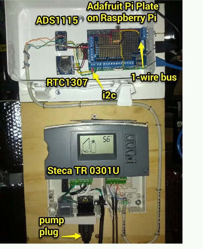
An Arduino Uno with ethernet shield and microSD storage was my first thought for a data logger. It is economical, available with great libraries, sample code and forum support. I got a little ways down the road using one and then realized it would be so much easier with a Raspberry Pi, add-on 16-bit ADC (ADS1115) and 1-wire thermal sensors (the ubiquitous Maxim ds18b20). My money making gig is as a Linux administrator, so working with Raspbian on the Pi is a simple pleasure for me. Also, getting Network Time Protocol (NTP) and a Real Time Clock (RTC) working on the Pi is simpler. I ended up getting a DS1307-based RTC that works over i2c. It's plenty accurate when paired with NTP which will give me good timestamps for my time series data. To make interfacing all these devices easier to my Raspberry Pi, I'm using the Adafruit Pi Plate (see below).

The ADC is used to read voltages on the two temperature sensors (located at the panel output header and storage tank) that came with the Steca controller. The voltage range that it presents is pretty small - 64F/2.040V - 176F/2.200 - so I'm happy having the 16-bit ADC rather than the Arduino's 10-bit ones. In the image below you can see how I have used and orange and green pair from CAT5 cable to tap into the roof and storage tank thermal probe leads.

I ordered 10 1-wire sensors from Amazon that were nicely soldered onto cables with stainless shrouds protecting the sensors. I hope they will withstand years of hot water temperatures. Five of them are now patched into a 12-port patch panel which I am using as a combined 1-wire and ethernet patch panel. The ethernet patch is for the Pi. For the 1-wire bus, three conductors in the CAT5 cable - blue (data), green (ground), and orange (power) - will extend the sensor wire to the panel. I'm using 568B wiring style in all the jacks regardless of whether it's ethernet or 1-wire. I borrowed a buddy's 110 impact punch down tool to connect all the wires easier (Thanks Peter!). Here's the back of the patch panel:

No comments:
Post a Comment